If you are the sort of person who likes to look at architectural drawings, this is your lucky day.
At least I hope that after you read today’s post you think this was your lucky day. I’ve decided that one area that I am hoping to focus on over the next year is better, more valuable, architectural content … and for me, that means I am going to try to take things in a more technical direction. While I don’t consider myself the most technical of architects, I do consider that aspect of the profession as part of my skill set from a design consideration. I put considerable effort into thinking about how something is going to be built as part of the design process – rather than determining how something should look and then sort of reverse-engineering my way backwards into the solution.
At any rate, today is the first of these more technically minded posts and I thought I would use a cabin project that I have been working on for some time as one of the vehicles for showcasing this information. But to start that process off, we need to talk about two things:
- The project itself, and
- The role that drawings play in this process
Let’s start by running through a quick description of the project.
This is my cabin project … and I mean “my” in every sense of the word except that a) I’m not paying for it, b) I won’t be living in it, and c) Ryan Thomason in my office has worked on this project as much as I have. This project is remotely located, fronts on to a beautiful lake, and is generally considered to be a wonderful place to live.
One piece of information that might be worth noting, is that there isn’t a lot of competition for contractors up here and I don’t have a lot of experience working on projects in cold weather environments – something that has led me to reading a lot of technical white papers on designing in heavy snow load areas.
Something else you should be made aware of, is that the site is densely forested – which you would not know based on looking at any of the drawings I am going to highlight in today’s post. Yes, I left them out for no other reason than I want to show the project, rather than a million tree trunks where there might be some sort of project.
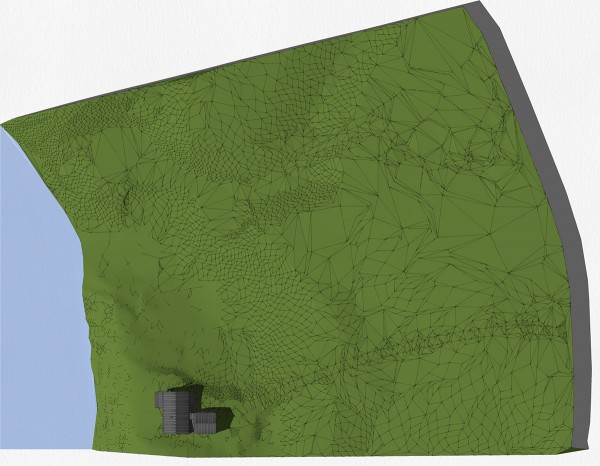
The image above is what this entire property looks like … I took this particular picture because I was 99% sure that I had just seen Bigfoot go running by.
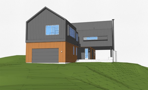
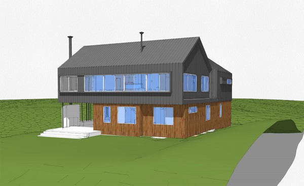
Here it is – my project. The image above is the approach and since the buildable footprint is so small (the goal was to leave every tree – all 2.37 million of them – intact on this site) the sequence of how the cabin will be built is also a consideration in the process. There is a garage with an isolated Master Bedroom Apartment Suite to the left, and on the right is an outdoor terrace that is covered by an elevated living/kitchen space. Through the covered terrace is the main view to the lake – this “hole” on the ground floor was purposeful so that the existence of the lake would not be completely blocked by the cabin.
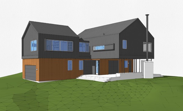
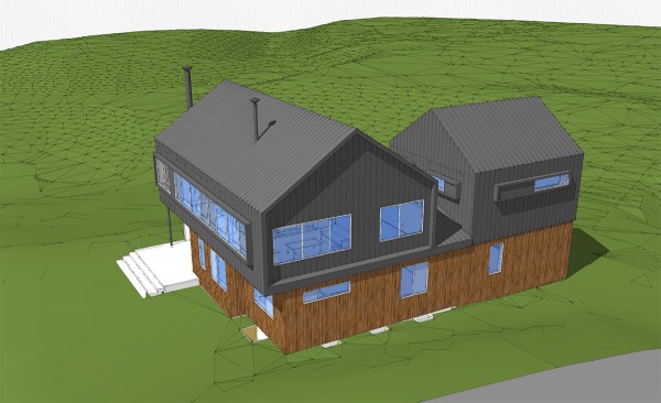
Working our way around, you can be a better look – and hopefully a better understanding – of the building massing. The main entrance to the cabin is in the corner where the two rectangular masses intersect one another.
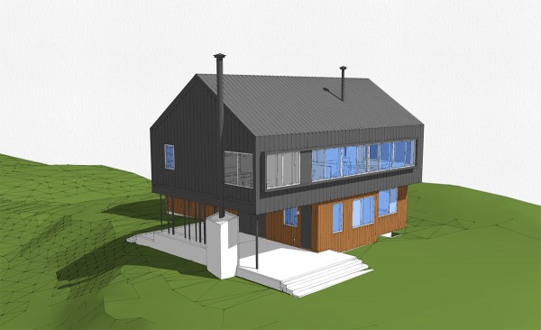
To get this particular view of the cabin, you would literally have to climb a tree – but – you could actually do that on this site. The massing is fairly clear but we have reinforced it with how we decided to delineate each component. This cabin will be capable of year round habitation, which meant that some consideration had to be given to the maintenance requirements and durability of the materials chosen. We elected to clad the entire ground floor level with unfinished, wire brushed, vertically oriented 11/16″ thick tongue & groove Ipe wood siding. On the upper level and roof, we are going with a 12″ wide standing seam pre-finished metal panel.
I’ll save the window information for another post but there are very large windows in this project – almost all of them are operable.
… and with screens. The bugs up here are biblical.
One thing that I noticed on one of my working site visits I noticed that the largest, uninterrupted expanse of glass that you saw on a majority of homes, was the size of a sliding patio door. The collection of windows ganged together on that upper level is 66″ tall and 24′ in length – uninterrupted. That is going to be one heck of a view towards the lake (and it didn’t hurt that the main living areas were placed on the upper level).
This view makes the separation of the Master Bedroom Apartment from the rest of the cabin pretty clear. On the ground floor level, you are looking at guest bedrooms (and light wells in to the basement). The large window on the second floor (from left to right) is the main living room, an upstairs playroom, a bathroom (on the inside wall of the Master Bedroom Apartment) and then a window in the master bedroom.
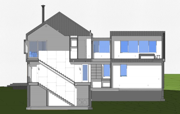
I thought it would be fun to through in a building section just so you could get a feel for how the spaces would be perceived on the inside of the cabin. This is through that main stair that connects all the levels together. There’s basically a 2-story steel-clad wall running from the basement all the way up in to the main living spaces on the upper level. To the right is the garage and a seating area in the master bedroom apartment.
But let’s get to the really interesting part – the construction drawings.
I should let you know that until I get permission from the owner’s, I will not be showing the actual complete floor plans … I might not even ask them. It’s one thing to use this blog as a teaching tool (at least, I hope it’s viewed as a teaching tool – that’s the goal) and another all-together to show the plans for someone else’s house. It’s a privacy thing that I take pretty seriously.
This construction set is incomplete and is a work in progress. Not ever having worked with our contractor before, we are trying to get a feel for how they work, what are they capable of building, how much pride do they take in their work, and where does the sweet spot exist between telling them every single possible piece of information and letting them be collaborators on the project.
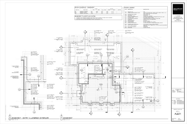
This first drawing is the basement level and since the vast majority of homes built-in this area are of the “log home” variety, the exactness that modern design requires is a new thing for these guys. Since I believe that you can fix a lot of construction issues after the fact, “crooked” walls are generally not one of them and foundation drawings are loaded with a lot of information. You can click all of these images and a much large image will open in a new window.
We did not have a positive experience with the initial foundation work – the first concrete contractor was resistant to doing things how we wanted and instead, wanted to rely on doing things they way he has always done them. He would call with questions – the irritation and frustration obvious in his voice – and ask us to clarify some information for him, while at the same time complain about how many drawings we were sending. Luckily for us, the contractor decided that he was not a good fit for this particular project and found someone else who is interested in the challenge of building a modern project.
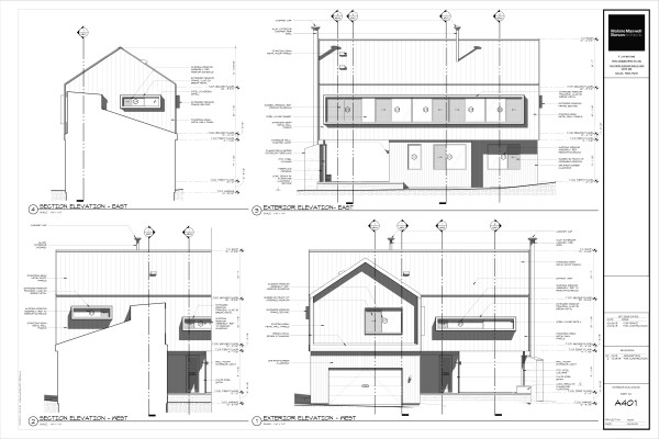
This is an example of our exterior elevation sheets. Normally we don’t show shadows – if for no other reason than contractor’s don’t build shadows – but we decided to make an exception this time. The building massing is so straightforward, (and the pen weight work in Revit still leaves a bit to be desired) we wanted to make sure that components of the house could be read in a 2D drawing. I don’t find them obnoxious or confusing and since we showed both versions (with and without shadows) to the contractor and asked his preference – the shadows remained in the set.
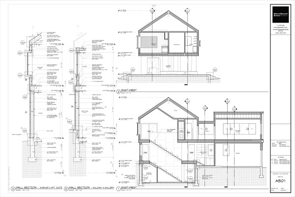
This is an example of a building section / wall section sheet. We don’t typically mix the two drawing types together, but my aversion to blank space on a sheet is stronger than my disdain for mixing drawing types. I don’t think it is all that common to show building sections in residential projects but again, this was about finding a tool that would allow the contractor to understand the spaces he was building. I wrote a piece a few months ago titled “The Incomplete Big Picture” about how important it was that the contractor have a commanding grasp of the entire project – that they are looking 10 steps in front while the subcontractors are only looking 1 or 2 steps in front. Building sections significantly contribute to that knowledge base.
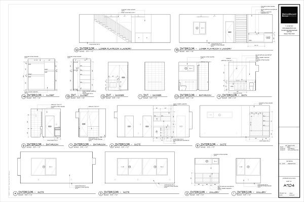
Interior elevations – pretty straight forward really. Our rule is that if there is something on a wall, the wall gets drawn. The normal context is to coordinate vertical dimensions on millwork, window placement, and the vertical coordination of outlets and wall switches.
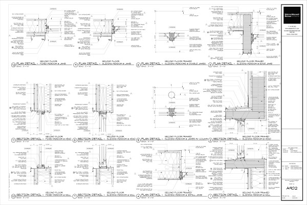
This is the real meat & potatoes of this particular job – detailing the building enclosure. (For those of you who are really observant and recognize the window details 1, 2, and 3 – you should note that these have been modified from when they were first published and we have added a layer of 1″ rigid insulation board). I think at current count, we have somewhere in the neighborhood of 63 details just for the exterior wall – and more are on their way.
Is it overkill? Maybe … if you don’t care whether or not everything aligns and matches up around the house. I like to think we take our jobs are architects in the old school manner – we are detailing how the building should be built, not just what it looks like.
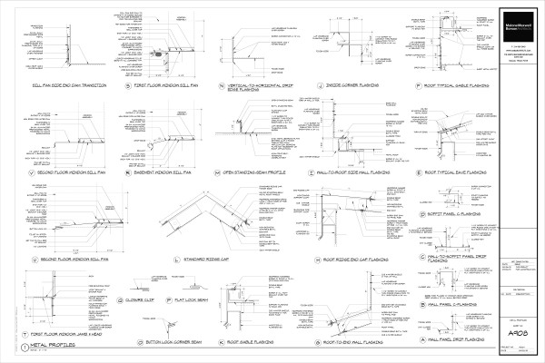
Here’s an example – actually, here’s 23 examples of what I am talking about. We (and by “we” I mean “Ryan”) have drawn and dimensioned all the flashing and brake metal components for this project.
I’ll be honest when I tell you that not all of our residential projects have drawings to this level of complexity and thoroughness. There are a handful of elements at work here that have created the situation that resulted in these drawings:
- We have clients that really care about getting things done correctly and they ask questions that drive the level of problem solving to a level that makes being an architect rewarding. I really like these people and I want them to think good thoughts about me (and Ryan) every time they use this cabin.
- We are working with a contractor that is excited about the project but will admit that they do not have the experience typically associated with building modern projects. This project is probably one of the smaller budget projects that they’ll building in 2016 but none-the-less, they’re smart enough to realize that more people are starting to see the advantages of living in a modern house and that more people will want a house like this one.
- The project is in an area of the country where the flow of energy through the wall is opposite when compared to the vast majority of our projects. As a result, we can’t sleepwalk through the process and let our instincts kick in.
- I plan on using this project as one of the main vehicles for my more technical posts in 2016. I want to start this process off right by making sure that the documentation is everything that it needs to be … and more.
I know that not everyone who comes to this site can read technical drawings, or that these same folks would be interested in really getting into the nuts and bolts – literally – of these projects, I will still try to keep things light and approachable on the site. I don’t really have any new goals for this blog, but I want to keep things interesting for me and for you (but mostly for me), so I hope you are as excited as I am for this new direction. If not, please accept my condolences in advance.
Cheers,


